Spur Gears vs Helical Gears: An OEM Buying Guide
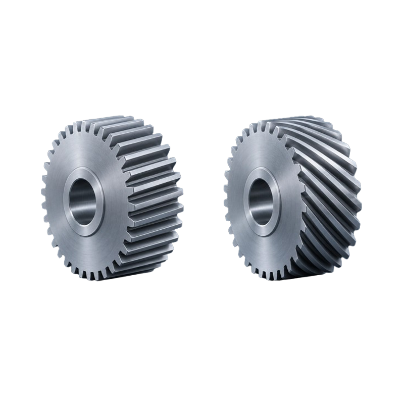
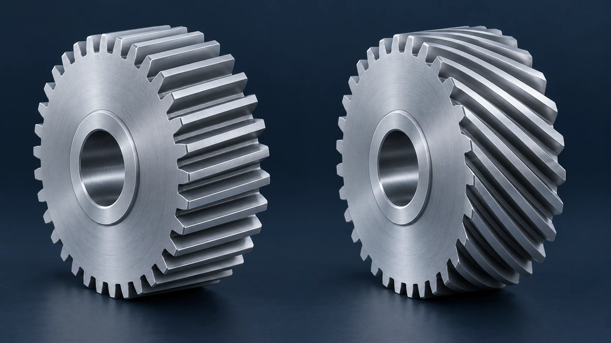
Spur gears use straight teeth and produce no axial thrust from an ideal parallel-axis mesh, while helical gears use angled teeth that engage progressively and generate axial thrust. Helical gearing can support smoother running, but its noise, load capacity, and efficiency depend on the complete design and operating conditions. Choose between the two by comparing the required motion, bearing arrangement, installation space, acceptance tests, and total assembly cost.
1. Start with the decision the machine requires
1.1 Confirm that the shafts are parallel
This comparison covers external spur and single-helical pairs transmitting motion between parallel shafts. Crossed-axis screw gearing, internal meshes, and double-helical arrangements need their own analysis. If the shaft layout is still open, begin with the broader OEM guide to gear types before narrowing the choice.
1.2 Use a comparison table to identify tradeoffs
The table below summarizes selection questions rather than assigning a universal winner. Its engagement and thrust distinctions follow KHK's helical gear explanation. The purchasing implications are a practical framework for reviewing a proposed drive with engineering.
| Decision factor | Spur pair | Single-helical pair | What to verify |
|---|---|---|---|
| Tooth direction | Straight, parallel to the shaft | Inclined at a specified helix angle | Geometry and mating drawing |
| Engagement | No overlap caused by helix | Progressive contact across the face | Contact behavior under actual load |
| Axial mesh force | Zero in the ideal mesh model | Must be carried through the supports | Thrust magnitude and direction |
| Noise target | May satisfy the specified duty | Often considered for smoother operation | Measured result at stated speed and load |
| Replacement fit | Match the retained pair geometry | Reference plane affects diameter | Center distance, hands, bearings, and clearances |
| Cost comparison | Quote the complete usable set | Include thrust support and assembly work | Parts, inspection, tooling, and validation |
1.3 Rank the requirements before requesting prices
Identify which requirements are fixed and which can change during development. A retained housing, a machine noise limit, and an aggressive part-price target can point toward different choices. Rank these constraints explicitly so a supplier can explain why a proposed configuration meets the project priorities.
2. Understand how the teeth enter contact
2.1 Read the straight tooth correctly
A spur gear's tooth trace runs parallel to its axis. In ideal aligned geometry, contact extends across the face without the axial progression created by a helix. This description does not mean that every spur mesh carries its load on only one tooth pair at a time.
2.2 Recognize the effect of a helix
In a helical mesh, contact develops across the face as the teeth rotate into engagement. This overlap can make the transfer of load more gradual. Its contribution depends on geometry, including face width and helix angle, so the word helical alone does not describe the complete contact condition.
2.3 Keep the theoretical picture connected to the part
The intended contact distribution assumes that the manufactured teeth and installed supports meet the design requirements. Shaft deflection or alignment errors can change where the load acts. Ask the design review to connect the selected tooth geometry to the stiffness and tolerances of the proposed assembly.
3. Turn a noise preference into an acceptance test
3.1 Describe the operating point
A request for quiet gears leaves the supplier without a measurable target. State the input speed, transmitted load, direction of rotation, and relevant machine operating modes. Include both steady running and transitions if a start, stop, or reversal creates the sound that matters to the customer.
3.2 Define how sound will be measured
Specify the sound metric, microphone position, enclosure condition, and measurement procedure. Record the background conditions so results from different test locations can be interpreted. Use a project-approved limit instead of assuming that a change to helical teeth guarantees a particular reduction in decibels.
3.3 Compare assemblies under equivalent conditions
Keep the motor, mounting, lubricant, temperature, and load consistent when comparing prototypes. Otherwise, a change elsewhere in the machine may be mistaken for a tooth-form improvement. Record the gear revisions and test configuration with each result so the accepted sample can be reproduced.
4. Compare load capacity on a common basis
4.1 Separate nominal torque from the duty cycle
Continuous torque is only one part of the load description. Give the frequency and duration of peaks, reversals, and overload events alongside the normal running condition. A comparison based on one nominal value can miss the operating event that controls the design.
4.2 Hold the comparison assumptions constant
Material condition, face width, gear size, life target, and reliability assumptions affect the capacity assessment. Ask for these inputs to be stated for both alternatives. A larger hardened helical gear and a smaller untreated spur gear do not isolate the effect of tooth direction.
4.3 Request the applicable engineering assessment
Ask the responsible engineer to identify the rating method and failure modes considered. The assessment should address the actual pair and its support conditions. Treat a catalog rating as applicable only within its stated assumptions, rather than transferring it to an unrelated custom component.
5. Calculate the helical mesh's axial thrust
5.1 Begin with tangential force
For a nominal force estimate, tangential force equals twice the transmitted torque divided by the applicable pitch diameter. Use meters for diameter when torque is in newton-meters and force is required in newtons. The force directions and distinction between spur and helical meshes are illustrated in KHK's gear force reference.
T: torque in N·m; d: pitch diameter in m; β: helix angle at that pitch cylinder; forces in N.
5.2 Work through a clearly defined example
Consider an illustrative unshifted helical mesh transmitting 100 N·m at a 100 mm reference diameter with a 20° reference helix angle. The nominal tangential force is 2 × 100 / 0.100 = 2,000 N, and axial force is 2,000 × tan 20° ≈ 728 N. These are calculated example loads, not an ABEJA product rating or a bearing selection.
5.3 Carry the force into the support review
The axial component is only one input to bearing and shaft design. Radial mesh forces, other external loads, duty, and the bearing arrangement also affect the result. Identify the load path through shoulders, retainers, bearings, and housing before treating the helical alternative as mechanically complete.
6. Review bearings and axial location together
6.1 Establish which support carries thrust
A bearing's position in the drawing should correspond to a defined role in the assembly. Show which support locates the shaft axially and how the other support accommodates the intended arrangement. Confirm load capacity, fits, and retention through the bearing review rather than adding an unspecified thrust bearing to a parts list.
6.2 Include reversals and back-driving
Thrust direction depends on helix hand and the direction of transmitted torque. A drive that reverses or is back-driven may load the supports differently from a single-direction operating case. Provide these states explicitly so the engineer can evaluate the relevant load directions and axial movement.
6.3 Distinguish mesh thrust from all shaft loads
An ideal spur mesh does not create the axial force associated with helical teeth. The shaft can still carry axial loads from other components or assembly conditions. Review the entire shaft before concluding that a spur-based machine needs no axial locating or load-carrying provision.
7. Specify the helical reference plane and hand
7.1 Label normal and transverse values
A helical drawing needs to identify whether module and pressure angle are normal or transverse values. The normal plane is perpendicular to the tooth trace, while the transverse plane is perpendicular to the shaft axis. A numerical module without that distinction can describe the wrong geometry.
7.2 Identify both members of the pair
For the external parallel-axis pair discussed here, the mating gears need opposite helix hands and equal helix-angle magnitudes. Their remaining tooth geometry must also be compatible. ABEJA's helical gear project page lists the pair and support information to bring into that review.
7.3 Keep assembly views unambiguous
Show the gear's hand as a drawing requirement instead of relying on a perspective rendering. Identify the shaft, mate, and viewing direction in any rotation or thrust sketch. These simple labels help prevent a mirrored image from being interpreted as an approved manufacturing definition.
8. Check center distance before a retrofit
8.1 Use the appropriate diameter equation
For spur gears, reference diameter is d = mz. For helical gears defined by normal module, it is d = mnz / cos β, with β measured at the reference cylinder. KHK's dimension calculations distinguish these systems and the additional treatment required for profile-shifted pairs.
8.2 Compare one hypothetical pair
An unshifted spur pair with module 2 and 40/80 teeth has reference diameters of 80 and 160 mm and a standard center distance of 120 mm. An unshifted helical pair with normal module 2, the same tooth counts, and a 20° helix has corresponding diameters of approximately 85.134 and 170.268 mm. Its standard center distance is approximately 127.701 mm, so it does not fit the original 120 mm geometry unchanged.
8.3 Treat a matching center distance as one check
A helical design using the same transverse module and tooth counts can preserve the nominal reference diameters. That does not settle thrust support, pressure-angle compatibility, outside clearances, or shaft interfaces. Evaluate the replacement pair and its assembly as a revised design before releasing a conversion.
9. Evaluate losses and temperature at machine level
9.1 Define the efficiency boundary
A quoted efficiency can describe a mesh, a gearbox, or an entire drive. Identify the input and output measurement points before comparing values. Keep bearing, seal, lubricant, and auxiliary losses within a consistent boundary for both proposed alternatives.
9.2 State the lubrication conditions
Share the lubricant specification, delivery method, operating temperature range, and maintenance arrangement. Ask the technical proposal to identify the lubrication assumptions used in its assessment. Do not infer the required lubricant or service interval from the words spur or helical alone.
9.3 Observe stabilized operation
A short unloaded demonstration may not reveal the temperature reached in production. Define the representative loaded cycle and the conditions for recording temperature. Use the resulting data to review the assembly's thermal behavior and repeat the comparison if the lubricant or enclosure changes materially.
10. Keep material and finishing in the comparison
10.1 Compare equivalent final conditions
Specify the material and final treatment condition for each candidate. If the alternatives use different conditions, ask why the difference is required and how it affects cost and acceptance. This keeps a materials decision visible instead of attributing every performance difference to the helix.
10.2 Ask what the finishing operation achieves
A finishing process should support a defined geometry or surface requirement. Ask which characteristics are controlled after treatment and what evidence will accompany the parts. The process name alone does not establish the noise level or life of the assembled drive.
10.3 Review the usable component
Include the bore, keyway, hub, shaft seats, and locating faces in the manufacturing scope. Their condition and relationship to the teeth matter when the part is assembled. ABEJA's spur gear specification page provides a starting point for connecting tooth geometry with those interfaces.
11. Separate accuracy, backlash, and positioning
11.1 Give accuracy requirements a complete identity
State the applicable standard, edition, and inspected characteristics when specifying an accuracy grade. Confirm how the measurements relate to the final part datums. A bare grade number cannot support a reliable comparison between quotations using different systems or inspection scopes.
11.2 Specify backlash with its conditions
Backlash is a property of the mesh under defined conditions, not a synonym for general machining accuracy. Identify its measurement form, mating member, center distance, and test setup. KHK's backlash reference explains why tooth thickness and installed settings belong in that discussion.
11.3 Test the output behavior that matters
A positioning application may care about lost motion after reversal or the final output's repeatability. State that requirement separately from a component tooth tolerance. Keep the motor control, couplings, supports, and complete transmission in the functional acceptance plan.
12. Plan installation and service access
12.1 Show the assembly sequence
Check how the gears, bearings, spacers, and retainers enter the housing. Confirm that the proposed axial location can actually be established during assembly. A component that fits the final drawing can still require an impractical installation sequence if access has not been reviewed.
12.2 Record the settings that affect the mesh
Identify the shims, locating features, and adjustments used to establish the approved arrangement. Connect those settings to the backlash and contact checks required by the project. Keep an assembly record so the prototype result does not depend on undocumented workshop adjustments.
12.3 Define the replacement unit
Decide whether service will replace an individual gear, a matched pair, or a larger module. Include access, identification, and retained-part inspection in that decision. This can change the practical cost of either gear type over the equipment's service life.
13. Compare the complete commercial scope
13.1 Separate recurring and one-time charges
Ask for production parts, samples, tooling, engineering work, and special inspection to be identified separately. State the same quantities and approval assumptions for both alternatives. This prevents a low prototype price from masking a different production or validation scope.
13.2 Include changes outside the gears
A helical proposal may require a revised bearing arrangement, housing feature, or assembly operation. A spur proposal may require other measures to achieve the machine's specified performance. Price the changes actually required by each design instead of assuming a fixed cost premium for one tooth form.
13.3 Consolidate the quotation package
Once the comparison identifies a preferred direction, issue one controlled set of requirements. The custom gear RFQ checklist can help organize that package. Keep any unresolved comparison assumptions visible in the supplier's written technical response.
14. Apply the comparison to practical scenarios
14.1 A retained housing with simple service needs
Consider a hypothetical machine whose existing spur pair meets its operating and noise requirements. If the housing and support arrangement must remain fixed, a compatible spur replacement may be the more direct option to investigate. Confirm the cause of replacement and retained-part condition before treating that preference as a final selection.
14.2 A new machine with a defined acoustic target
Consider a new enclosed drive where the customer has specified an acoustic acceptance test. A helical concept merits review because of its progressive engagement. Carry its thrust loads, bearing layout, and validation cost through the same concept review rather than judging the gears in isolation.
14.3 A frequently reversing positioning axis
For a reversing axis, investigate both lost motion and the support response to changes in torque direction. Neither gear family removes the need for a defined backlash and output-positioning requirement. Select the configuration that demonstrates the required behavior in the proposed assembly.
15. Use a documented selection worksheet
15.1 Record the evidence behind the choice
Use the following original worksheet during the design and purchasing review. Complete both candidate columns before approving a preferred option. An open field should identify the needed information and its owner instead of becoming an undocumented assumption.
| Review item | Spur candidate | Helical candidate |
|---|---|---|
| Fixed geometry | Pair drawing; center distance; interfaces | Pair drawing; reference plane; helix hands |
| Duty and capacity | Common duty; assessment reference | Same duty; assessment reference |
| Supports | Shaft loads; locating arrangement | Mesh thrust; load directions; locating arrangement |
| Acceptance | Noise, backlash, temperature, and output tests | Equivalent test conditions and limits |
| Complete cost | Parts; tooling; assembly; validation | Parts; support changes; tooling; validation |
| Release decision | Evidence; open questions; approver | Evidence; open questions; approver |
15.2 Make exceptions part of the decision
A proposed option may satisfy most requirements while depending on one unresolved change. Record that dependency beside the affected requirement and assign an approval owner. Release the selection only against the agreed configuration and evidence, including any accepted deviations.
15.3 Bring the pair into an ABEJA discussion
Share the candidate drawings and completed comparison through ABEJA Gears' inquiry page. Include the required operating duty and the result you need the comparison to establish. Confirm the offered manufacturing scope, inspection records, and project terms in the resulting quotation.
16. Frequently asked questions
16.1 Are helical gears always quieter than spur gears?
Helical engagement can support smoother running, but it does not guarantee the quieter finished machine in every comparison. Manufacturing accuracy, mounting, speed, load, and the surrounding assembly affect the measured result. Compare the actual candidates using the same defined acoustic test.
16.2 Can I replace spur gears with helical gears directly?
A direct replacement requires more than matching tooth counts and an unlabeled module value. Review both gears, reference plane, center distance, helix hands, pressure angles, and the added thrust load path. Treat the change as an assembly design review even when the nominal center distance can be preserved.
16.3 Which option should an OEM choose first?
Begin with the option that best fits the fixed layout and measurable operating requirements. Compare the competing design when it offers a relevant benefit that can be demonstrated within the project constraints. Make the final decision from the documented engineering and cost comparison rather than a universal spur-versus-helical ranking.
Related Posts
Rack and Pinion Sizing: An OEM Selection Guide
Gear Backlash: How to Specify and Measure It

Gear Module vs Diametral Pitch: A Buyer’s Guide