
Gear Backlash: How to Specify and Measure It
Gear backlash is the clearance between mating tooth flanks, commonly expressed as circumferential distance or free angular movement with one member held stationary. Specify an acceptable range together with the gear pair, measurement direction, installed geometry, temperature, and test load. Measure the assembled mesh at multiple positions, then check contact and running behavior before approving an adjustment.
1. Define the clearance you actually need to control
1.1 Identify backlash at the tooth flanks
Backlash describes the available movement between opposite tooth-flank contacts in a mesh. KHK's backlash reference distinguishes circumferential, normal, and angular forms of this clearance. Naming the form matters because the same numerical value in different directions does not necessarily represent the same mesh condition.
1.2 Separate backlash from tip clearance
Tooth-tip clearance is the space between a tooth tip and the opposing root region. Backlash concerns the tooth flanks that transmit motion when the direction of contact changes. A photograph showing space below a tooth does not establish the backlash value that an inspector should accept.
1.3 Separate mesh clearance from machine lost motion
A machine's reversal movement can include gear backlash, coupling play, bearing movement, and elastic deflection. Decide whether the acceptance requirement applies to one gear mesh or the complete output axis. Use separate names and test conditions when both quantities must be controlled.
2. Choose a measurement form and reference location
2.1 State linear or angular units explicitly
A requirement such as backlash 0.1 is incomplete. Identify millimeters, degrees, or arcminutes and name the member or reference circle to which the value applies. For helical gearing, also identify the relevant plane if the requirement uses linear tooth clearance.
| Quantity | What the value describes | Information needed with it |
|---|---|---|
| Circumferential backlash | Arc movement at the specified pitch circle | Gear member, pitch radius, installed condition, and units |
| Normal backlash | Clearance measured in the relevant normal direction between flanks | Tooth system, plane, and conversion basis |
| Angular backlash | Free angular movement of one member with the other held | Measured shaft, restrained member, and angular units |
| Axis reversal lost motion | Observed output movement during a defined reversal test | Entire drive configuration, applied load, and test procedure |
2.2 Identify the measured shaft
An angular value at the pinion is not automatically the same numerical value at a larger mating gear. Their radii differ, so the same circumferential clearance corresponds to different angular movements. State the measured shaft in the drawing note and inspection report rather than relying on an assembly sketch alone.
2.3 Keep indicator readings distinct from converted results
A dial indicator observes displacement at its contact point. If that point is away from the specified pitch circle, its reading requires an appropriate geometric conversion. Record the contact location, direction, and radius so another inspector can reproduce the result.
3. Specify a range instead of an unsupported minimum
3.1 Establish both limits from the application
The acceptable backlash range belongs to the particular gear pair and machine requirement. The lower bound must accommodate the approved geometry and operating conditions, while the upper bound must support the required motion and performance. Ask the responsible designer to establish these limits instead of copying a catalog value from an unrelated gear.
3.2 Avoid treating zero clearance as the default
Closing an ordinary fixed-center gear pair until no movement is detectable can produce a tight mesh. KHK's backlash guidance warns that eliminating the clearance can impair smooth rotation. A deliberately preloaded system needs its own design and acceptance method, including the load range over which its behavior is required.
3.3 Keep measurement capability visible
A very narrow acceptance band needs a measurement method capable of distinguishing acceptable and unacceptable results. Agree instrument resolution, repeatability, and the treatment of uncertainty with the inspection team. Do not add decimal places to a purchase requirement without checking whether the proposed test can support them.
4. Connect backlash to tooth thickness and center distance
4.1 Review the manufactured tooth thickness
Tooth thickness is one design and manufacturing input to the clearance between mating gears. A pair can use intentional tooth thinning to provide the required backlash at its specified center distance. Keep the tooth-thickness inspection requirement separate from the assembled backlash test, since they establish different evidence.
4.2 Control the installed spacing
For an external parallel-axis involute pair, increasing center distance generally increases backlash, while decreasing it reduces backlash. KHK's mounting accuracy guidance also explains how spacing changes affect mesh contact. Adjust spacing only within the approved design range and check more than the clearance reading.
4.3 Confirm the geometry before changing settings
An incorrect mating pitch or pressure angle is a compatibility problem, not a backlash adjustment task. Verify both members against the controlled drawings before changing the housing or supports. ABEJA's spur gear specification page connects these geometry inputs with the shaft interfaces used in assembly.
5. Include the supports in the measurement
5.1 Check that the shafts remain located
A backlash test is meaningful only when the shafts occupy the intended positions. Loose retention or movement in the fixture can appear as additional tooth clearance. Check the locating arrangement before interpreting a large reversal reading as evidence that the gears were cut incorrectly.
5.2 Account for axial freedom in helical gearing
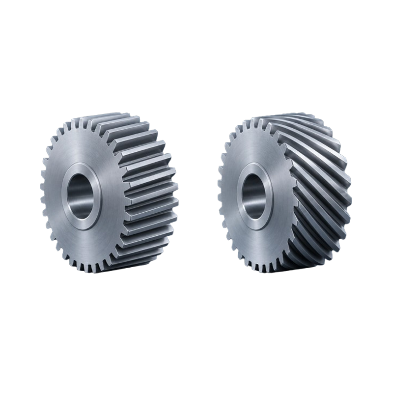
Axial movement in a helical assembly can change the relationship between tooth position and shaft rotation. Define the axial restraint and measurement condition in the test setup. The pair and support information on ABEJA's helical gear project page is relevant when establishing that condition.
5.3 Inspect the reference surfaces
Burrs, debris, or incomplete seating can prevent the intended mounting geometry from being achieved. Inspect the functional mounting surfaces and record any corrected condition before repeating the test. This creates a useful distinction between an assembly correction and a change to the gears themselves.
6. Define temperature, lubricant, and test load
6.1 Record the thermal condition
A room-temperature measurement should be identified as such when the machine operates under different thermal conditions. Expansion of the gears, housing, and supports can affect the installed relationship, and its net effect depends on the assembly. Define any required cold and operating-condition checks rather than assuming that heating always changes backlash in one direction.
6.2 Keep the lubrication condition consistent
Use the agreed lubricant and preparation condition when comparing inspection results. A change in lubrication or contamination can change how the operator senses contact during a low-load check. Record departures from the procedure so an inconsistent setup is not mistaken for a dimensional change.
6.3 Specify the reversing effort
The effort used to move a gear between opposite contacts affects what a test captures. Excessive force can add elastic movement from shafts, fixtures, or supports to the apparent free motion. Define a repeatable test torque or force with engineering and identify whether loaded system deflection is intentionally included.
7. Prepare a repeatable inspection setup
7.1 Identify the exact mating pair
Record both part numbers, revisions, and relevant identification marks before testing. Note whether the mate is the production component, a reference component, or a master used for inspection. Those configurations need not produce identical results and should not be mixed in one acceptance record.
7.2 Restrain one member through a defined fixture
Hold one member stationary using the approved inspection arrangement. Verify that the restraint does not introduce unmeasured movement or distort the mounting condition. Conduct the static check with unintended machine motion prevented and follow the equipment's inspection procedure.
7.3 Align the measuring device
Position a displacement indicator to sense the intended motion at a known location, or use a suitable angular measurement device. Misalignment between the measured motion and indicator direction can distort the reading. Document the setup with a sketch or photograph that shows the reference point clearly.
8. Measure between opposite flank contacts
8.1 Establish the first contact gently
Move the free member toward one flank contact using the agreed test effort. Establish the reference reading without continuing to load the fixture beyond that condition. The purpose is to locate the measurement endpoint consistently, not to force the gear against its mate.
8.2 Reverse to the other contact
Reverse the free member with the same defined method and record the movement to opposite flank contact. Confirm that the restrained member stayed stationary. If the fixture moved or the contact endpoint was uncertain, correct the setup and repeat the measurement instead of averaging an invalid reading.
8.3 Repeat the check at the same position
Repeated readings at one mesh position reveal whether the procedure is stable enough to use. Record the individual results before deciding that the part itself varies. A repeatability problem should be resolved before expanding the test to more gear positions.
9. Convert an angular reading into circumferential clearance
9.1 Define the radius and angle
Circumferential backlash at a stated circle follows the arc-length relationship j = rθ. Use radians for θ and the same length unit for radius r and backlash j. This conversion concerns one measured gear member with its mate held and does not remove fixture movement or elastic deflection from the reading.
j: circumferential backlash in mm; r: specified pitch radius in mm; d: its diameter in mm; θdeg: measured angular backlash in degrees.
9.2 Calculate a hypothetical inspection result
Assume an unshifted spur gear has an 80 mm pitch diameter at the test condition and measured angular backlash of 0.10°. Its pitch radius is 40 mm, giving j = 40 × 0.10 × π / 180 ≈ 0.0698 mm. The angular reading is also 6 arcminutes, and the example is a conversion exercise rather than a recommended acceptance limit.
9.3 Do not use the tooth-tip radius by default
An indicator reading at a tooth tip does not automatically equal pitch-circle backlash. Its measurement radius and direction must be included in the conversion, with a small-angle approximation identified where used. If the geometry of the contact point is uncertain, choose a more clearly defined measurement setup.
10. Map variation across the mesh
10.1 Inspect more than one angular position
A single backlash reading cannot show variation around a rotating pair. Use an agreed sampling plan that covers the relevant gear positions and retains the location of each reading. If engineering requires a more complete contact-cycle assessment, specify that coverage explicitly instead of assuming one shaft revolution covers every pairing of teeth.
10.2 Retain minimum and maximum results
An average backlash value can hide a tight mesh position or a position with excessive tooth clearance. Report the measured backlash range and its gear positions alongside any average requested by the project. KHK's gear accuracy reference distinguishes pitch, profile, helix, and runout characteristics that may warrant separate investigation.
10.3 Map a rack along its working travel
For a rack-and-pinion assembly, record the linear position of each backlash check. Include section transitions when joined racks are used. ABEJA's gear rack project page treats full-stroke and joint checks as part of the axis specification.
11. Check contact and operation alongside backlash
11.1 Inspect the agreed contact condition
A backlash value inside its limits does not prove that load is distributed acceptably across the teeth. Perform the contact check required by the design using the specified setup and load condition. Retain the record with the backlash results so neither check becomes a substitute for the other.
11.2 Confirm the relevant running behavior
Noise, temperature, vibration, and reversal behavior are separate acceptance outcomes when the machine specification requires them. Test those outcomes at their defined operating conditions. A static clearance measurement alone cannot demonstrate how the completed drive behaves under production load.
11.3 Use gear-family-specific procedures
Bevel and worm assemblies require their own mounting and contact review. Do not apply a simple external spur center-distance adjustment as a universal procedure for every gear family. Follow the pair drawing and approved installation method for the actual arrangement.
12. Adjust backlash without creating another problem
12.1 Identify the permitted adjustment
Use only the adjustment method allowed by the assembly design. It may involve an approved spacing or locating feature rather than any convenient direction of movement. Check how the change affects contact, retention, clearances, and other parts before making it permanent.
12.2 Check the tightest measured location
A setting that improves a loose position can make another position too tight. Repeat the specified position map after an adjustment and preserve both the previous and revised settings. Accept the assembly against its full required range rather than the most favorable reading.
12.3 Investigate conditions outside the adjustment range
If the approved adjustment cannot achieve the requirement, stop treating the problem as a setting exercise. Review mating geometry, tooth thickness, mounting dimensions, and part condition with engineering. Modifying teeth or mounting faces without that review can obscure the original cause and invalidate the controlled drawing.
13. Define what an anti-backlash arrangement promises
13.1 Describe the preload mechanism
Split gears, paired drives, and other preloaded arrangements manage reversal behavior through a defined mechanism. State how the preload is established and what load range the design must accommodate. A label such as zero backlash is insufficient unless the measurement method and operating conditions accompany it.
13.2 Evaluate the operating tradeoffs
Preload creates internal loading that belongs in the engineering assessment. Ask how it affects friction, temperature, wear, and the allowable external duty for the proposed arrangement. Require evidence for the actual design instead of assuming that adding preload improves every operating characteristic.
13.3 Separate control compensation from physical clearance
Control compensation can alter commanded motion during a reversal, but it does not physically change the tooth clearance. Validate the resulting axis behavior across the loads and directions the machine will encounter. Keep mechanical acceptance and compensated motion acceptance identifiable in the test plan.
14. Use symptoms to choose the next inspection
14.1 Start with the pattern in the measurements
Use a symptom to select a check, not to declare a cause without evidence. The table below is an original troubleshooting aid for organizing that review. Each result should be compared with the controlled dimensions and test procedure before a component is rejected.
| Observation | Checks to consider | Evidence to retain |
|---|---|---|
| Large reading at every sampled position | Spacing, tooth thickness, fixture movement, and correct mate | Installed dimensions and repeatable position map |
| Variation around a revolution | Seating, eccentricity, tooth geometry, and shaft location | Indexed readings and relevant geometry reports |
| Change after warming | Thermal condition, support location, and measurement consistency | Temperature, elapsed operation, and cold/warm results |
| Large machine reversal error despite acceptable mesh clearance | Couplings, supports, other stages, compliance, and controls | Local mesh test and separate output-axis test |
| Local change at a rack joint | Joint pitch alignment, mounting height, and retention | Position-linked measurements on both sides of the joint |
14.2 Compare new and retained components
Replacing one gear changes the relationship with the retained mate. Inspect the retained part and record whether its condition satisfies the replacement assumptions. A measurement after replacement should not be attributed solely to the new part without examining that relationship.
14.3 Preserve evidence before altering the assembly
Before correcting a backlash problem, record the original clearance readings, installed settings, and identification of both mating components. Change one identified condition at a time where practical, then repeat the same measurement method and position coverage. Comparing those records helps distinguish the effect of an assembly change from a change in the test itself.
15. Put the requirement into a usable acceptance note
15.1 Complete the inspection fields
A usable backlash note combines limits with the conditions that make them reproducible. Complete the fields below with project-approved values and references. Leave unresolved fields explicitly open until the designer and inspection team agree the method.
Pair and setup: part numbers and revisions; mating or reference member; installed spacing and support condition.Quantity: circumferential, normal, or angular backlash; measured member; reference plane or radius; units; minimum and maximum limits.Method: restrained member; instrument; reversing effort; temperature and lubricant condition; position coverage; repeatability and uncertainty treatment.Acceptance evidence: individual readings, measured extremes and locations, contact checks, required running tests, and approval owner.
15.2 Include the note in the supplier's scope
Make the acceptance note part of the controlled inquiry rather than an expectation added after samples arrive. Ask the offer to identify the fixture, measurements, and reports included. The broader custom gear RFQ checklist helps connect this test requirement with the rest of the order.
15.3 Request a review of the actual mesh
Share the pair drawings, operating conditions, and proposed measurement note through ABEJA Gears' inquiry page. Explain whether the task concerns a new design, incoming inspection, or a replacement problem. Confirm the available manufacturing and inspection scope in the resulting written response.
16. Frequently asked questions
16.1 What is a good backlash value for a gear?
There is no single value suitable for every gear pair. The acceptable range depends on geometry, installation, duty, temperature, and the required machine behavior. Use a designer-approved range with a defined measurement method instead of a universal number.
16.2 Does a higher accuracy grade guarantee less backlash?
An accuracy grade does not, by itself, define the assembled backlash. Tooth-thickness requirements, the mating member, and installed geometry still need to be specified. Name the applicable standard and edition and keep the backlash acceptance note separate.
16.3 Is one dial-indicator reading enough?
One reading describes one setup and one mesh position. It does not show repeatability or variation across the required rotation or travel. Use the agreed position coverage and report the measured range before accepting the assembly.
Related Posts
Rack and Pinion Sizing: An OEM Selection Guide
Gear Backlash: How to Specify and Measure It

Gear Module vs Diametral Pitch: A Buyer’s Guide