
Rack and Pinion Sizing: An OEM Selection Guide
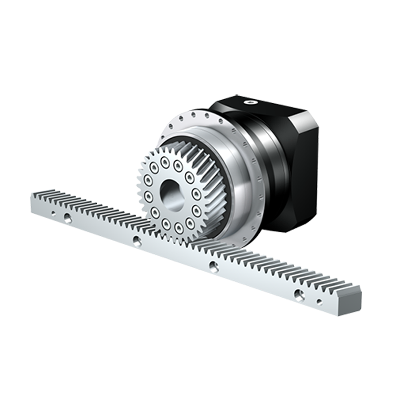
Rack and pinion sizing starts with the required linear force, speed, acceleration, and working stroke. Use the pinion's pitch geometry to calculate travel per revolution, rotational speed, and nominal torque, then check tooth capacity, supports, mounting, and positioning requirements. A geometry calculation is an initial selection step; the selected rack, pinion, reducer, and motor still need assessment against the complete operating cycle.
1. Define the linear task before choosing a module
1.1 Identify what moves and what stays fixed
A rack-and-pinion drive converts pinion rotation into relative linear motion along the rack. State whether the rack moves past a fixed pinion or the pinion travels with a carriage along a fixed rack. This choice affects which mass accelerates and where the motor, cable routing, and supports must fit.
1.2 Separate drive force from guided load
The force that drives an axis is not automatically equal to the payload's weight. A horizontal carriage requires an acceleration and resistance assessment, while an inclined or vertical axis also needs the relevant gravity component. The linear guides and structure must carry the loads assigned to them rather than relying on an unspecified rack mounting arrangement.
1.3 List the fixed project constraints
Record the required stroke, available envelope, retained components, and output-motion criteria. Identify which of these can change during selection. ABEJA's gear rack project page organizes the rack, pinion, base, and full-stroke requirements into one specification discussion.
2. Build a motion and load profile
2.1 Include acceleration and deceleration
The axis load changes as the carriage accelerates, runs at speed, and decelerates. Record the moving mass, acceleration, process force, and resistance for each relevant phase. Include the moving drive equipment when it travels with the carriage, rather than counting only the workpiece.
2.2 Distinguish continuous duty from peaks
Peak force and continuous force serve different selection decisions. Give the duration and repetition of each peak alongside the cycle time and resting periods. This allows the drive assessment to address both short events and repeated thermal or fatigue loading.
2.3 Describe reversals and exceptional events
Direction changes can alter the load path and expose lost motion in the complete axis. Identify normal reversals separately from jams, emergency stops, or other exceptional conditions. Ask engineering to define which events the transmission must sustain and which are limited by a separate protective arrangement.
3. Match the rack and pinion tooth system
3.1 Confirm pitch and pressure angle
The rack and pinion need compatible tooth geometry, including pitch and pressure angle. Module, diametral pitch, and circular pitch describe related quantities but cannot be interchanged by copying their numerical values. The guide to module and diametral pitch explains how to preserve the controlling designation during conversion.
3.2 Identify helical reference planes
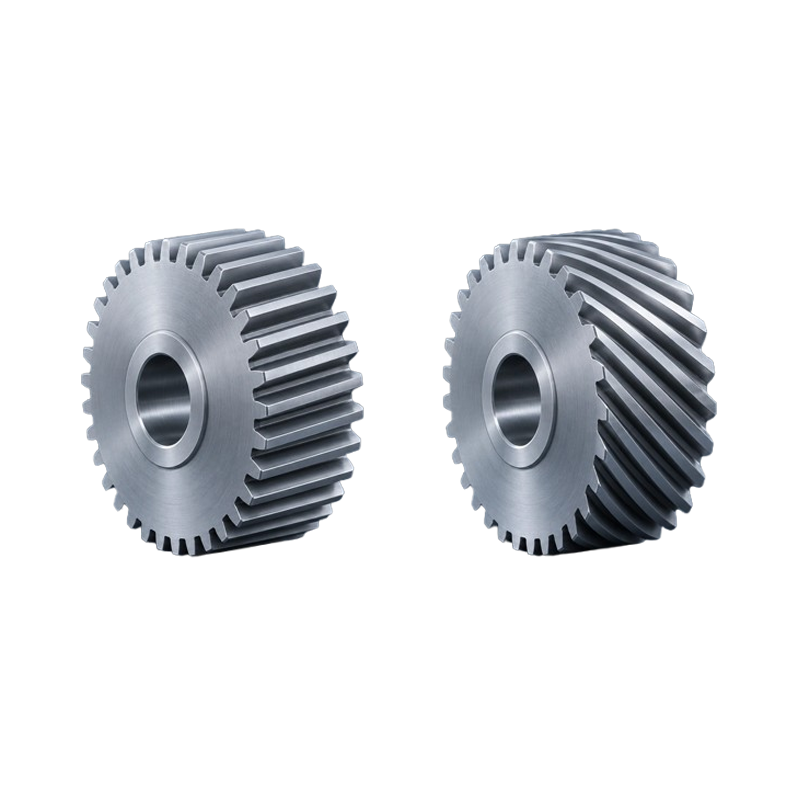
A helical rack specification must identify normal or transverse module, the corresponding pressure angle, helix angle, and mating hand. The travel calculation uses the pinion geometry in the transverse plane. Confirm the actual rack-and-pinion combination instead of assuming that equal unlabeled module values establish compatibility.
3.3 Understand circular-pitch alternatives
A circular-pitch designation directly specifies tooth spacing along the relevant pitch direction. For a compatible straight rack and pinion, travel per pinion revolution equals circular pitch multiplied by pinion tooth count. KHK's CP rack technical guide illustrates this approach; a convenient travel increment does not itself guarantee axis accuracy.
4. Calculate travel per pinion revolution
4.1 Use reference pitch geometry
For a standard straight rack and spur pinion, travel per revolution is L = πmz, where m is module and z is the pinion tooth count. It is also πd because the pinion reference diameter is d = mz. KHK's rack-and-spur dimension calculations describe this relationship between rotation and linear displacement.
d: pinion reference diameter in mm; m: module in mm; z: tooth count; L: nominal travel in mm per revolution.
4.2 Keep outside diameter out of the travel formula
Pinion outside diameter measures the envelope over the tooth tips. It is not the pitch diameter used to calculate linear travel. Use the controlled pitch geometry from the drawing rather than a caliper measurement across the tips.
4.3 Separate geometry from actual position
Calculated travel describes ideal kinematics. Actual axis position also depends on tooth accuracy, installation, deformation, backlash, and the control system. Keep the travel-per-revolution calculation separate from the machine's positioning and repeatability acceptance tests.
5. Convert linear force into nominal pinion torque
5.1 Calculate the force along the travel direction
For a simple horizontal example, the drive force can be written as moving mass times acceleration plus opposing process and resistance forces. Use a consistent sign convention when a force assists motion or the axis decelerates. Add gravity along the travel direction when the actual axis orientation requires it.
5.2 Apply the pinion lever arm
Ideal pinion torque equals the tangential driving force multiplied by the pinion pitch radius. Use meters for radius when force is in newtons and torque is required in newton-meters. KHK's gear force reference distinguishes the mesh-force components that must then be carried by the gears and supports.
F: force along rack travel in N; d: pinion pitch diameter in m; Tideal: ideal pinion torque in N·m, before losses and additional inertial terms.
5.3 Assess the other force components
The force that propels the rack is not the only load on the pinion support and mounting structure. Tooth pressure angle produces a separating force, and a helical arrangement introduces additional directional considerations. Include these components in the support assessment instead of sizing the bearing or rack fasteners from the driving force alone.
6. Convert axis speed into pinion speed
6.1 Calculate revolutions from travel
Pinion speed equals linear speed divided by travel per revolution when the time units match. If v is in meters per second and L is in meters per revolution, n = 60v / L gives revolutions per minute. Keep the unit conversion visible because mixing millimeters with meters introduces a large error.
6.2 Check the entire speed range
The maximum travel speed establishes only one point in the motion profile. Include slow approach, indexing, and reversal conditions in the drive discussion. The selected motor, reducer, and control arrangement must meet the relevant requirements across that range.
6.3 Understand the diameter tradeoff
At a fixed linear speed, a larger pinion pitch diameter requires fewer revolutions per minute. At a fixed driving force, that larger radius requires more ideal torque. This tradeoff helps compare candidate geometries, but it does not establish their tooth strength or available installation space.
7. Work through one horizontal-axis example
7.1 State the assumed duty
Consider a hypothetical horizontal axis with 250 kg of total moving mass, acceleration of 1 m/s², and 150 N of opposing process and resistance force during acceleration. Its simplified linear driving force is 250 × 1 + 150 = 400 N. Assume a straight module 2 rack, a compatible 30-tooth spur pinion, and a calculation point at 0.30 m/s; these are illustrative inputs rather than a selected product specification.
7.2 Calculate geometry, torque, and speed
The pinion reference diameter is 2 × 30 = 60 mm, and ideal travel per revolution is π × 60 ≈ 188.496 mm. At 400 N, ideal pinion torque is 400 × 0.060 / 2 = 12 N·m. At 0.30 m/s, the corresponding pinion speed is approximately 95.493 rpm.
7.3 Identify what the example leaves open
The 12 N·m result does not include losses, rotating inertia, or any additional design factors required by the application. It does not prove that a particular module 2 rack or pinion can carry the duty. Tooth strength, surface durability, shaft interfaces, supports, and the full motion cycle still require assessment.
| Pinion teeth | Reference diameter | Travel per revolution | Pinion speed | Ideal torque |
|---|---|---|---|---|
| 20 | 40 mm | 125.664 mm | 143.239 rpm | 8 N·m |
| 30 | 60 mm | 188.496 mm | 95.493 rpm | 12 N·m |
| 40 | 80 mm | 251.327 mm | 71.620 rpm | 16 N·m |
8. Carry the calculation through the reducer and motor
8.1 Define the reduction ratio
Define reduction ratio i as motor speed divided by pinion speed for this calculation. Motor speed is then i times the required pinion speed. State the convention explicitly so an inverse ratio from another drawing is not inserted into the calculation by mistake.
8.2 Use a clearly bounded efficiency assumption
For illustration, assume i = 10 and an overall mechanical efficiency η = 0.90 from the motor shaft to useful rack motion at the stated operating point. The example's motor torque contribution for the 400 N linear load is 12 / (10 × 0.90) ≈ 1.333 N·m, with motor speed approximately 954.930 rpm. This assumed efficiency is not a supplier claim, and additional rotating inertia and other omitted loads still need to be included.
8.3 Complete the motor duty assessment
Motor selection requires the torque-speed demand across the whole cycle, not only the illustrative operating point. Include acceleration of rotating components, peak duration, repeated duty, braking, and any holding requirement. Check those demands against the proposed motor and reducer data with the responsible drive engineer.
9. Select tooth size and face width through a capacity review
9.1 Assess both rack and pinion
The selected pair must satisfy the relevant tooth bending and surface-durability requirements. Check both members because their material, treatment, geometry, and operating exposure may differ. KHK's rack technical information distinguishes its catalog assumptions from calculations using the actual application conditions.
9.2 State what the capacity calculation assumes
Record the load cycle, life target, material condition, lubrication, and load-distribution assumptions used in the assessment. Identify the rating method and the design factors selected by engineering. Do not transfer a different manufacturer's stock-rack force rating to an ABEJA quotation or an unassessed custom pair.
9.3 Review usable face contact
A nominally wider tooth does not guarantee that the installed pair uses the whole face effectively. Alignment, support deflection, and the approved tooth geometry influence contact. Ask the review to connect the proposed face width with the mounting and support conditions used to justify it.
10. Choose straight or helical teeth in the axis context
10.1 Evaluate a straight-tooth arrangement
A straight rack and compatible spur pinion provide a direct geometry for the initial travel and torque calculations used here. Assess whether the proposed pair meets the axis's running, noise, and positioning requirements. Keep those requirements measurable rather than assuming that a simple tooth form is suitable for every duty.
10.2 Include helical geometry and support loads
A helical rack-and-pinion proposal needs its own mating geometry and force review. Its normal module cannot be substituted directly into a transverse travel calculation without accounting for helix angle. ABEJA's helical gear project guidance identifies the reference-plane and support information to include in that discussion.
10.3 Compare the proposed assemblies
Compare straight and helical candidates at the same required force, speed, motion cycle, and acceptance criteria. Include their support, installation, inspection, and service requirements in the cost comparison. Treat noise or positioning benefits as results to demonstrate for the proposed axis, rather than guaranteed outcomes of the tooth-form label.
11. Size the usable stroke and plan section joints
11.1 Distinguish rack length from working travel
Physical rack length does not by itself define the approved machine stroke. Show the pinion's required engagement at both travel limits and include the installation's end-clearance and overtravel provisions. Review the complete motion envelope before ordering lengths or machining the base.
11.2 Control pitch across each joint
A joint between rack sections must preserve the intended tooth-spacing transition. KHK's rack application guidance explains why some end-machined rack designs require controlled spacing rather than simply closing the visible gap. Use the specified joining method for the selected rack design and verify the transition after mounting.
11.3 Identify segments and replacement expectations
For a multi-section rack installation, record each segment's sequence, orientation, joint locations, and any matching requirements. State whether a future replacement segment must interchange individually or needs renewed alignment with neighboring rack sections. This information helps purchasing define the spare component and the installation checks needed before returning the axis to service.
12. Define the mounting geometry and load path
12.1 Reference the pitch-line height
For a standard unshifted spur pinion and rack, nominal mounting distance from the rack base datum to the pinion axis combines rack pitch-line height and pinion pitch radius. Confirm the actual drawing when profile shift or another geometry is used. The tooth-tip height is not a substitute for the specified pitch-line reference.
12.2 Keep the installation consistent along the stroke
The rack base and pinion support must maintain the specified relationship across the travel. Check mounting datums, alignment, and retention at the locations required by the project. Include the section joints in that assessment because a locally shifted segment changes the mesh condition.
12.3 Design retention for the complete load case
Rack fasteners, locating features, pinion shaft interfaces, and supports all form part of the load path. Assess them for the actual force directions, reversals, and exceptional loads assigned to the design. Confirm access for assembly and maintenance before accepting an arrangement that works only in a sectional drawing.
13. Separate tooth precision from axis positioning
13.1 Specify accuracy and repeatability separately
Positioning accuracy concerns how actual position compares with the intended position, while repeatability concerns the consistency of repeated approaches under defined conditions. Give each required result its own test procedure and limit. State the approach direction, load, temperature condition, and travel positions used for acceptance.
13.2 Include reversal and compliance
Tooth backlash is one contributor to axis reversal behavior. Reducer play, coupling movement, structural compliance, and the control arrangement can also affect the observed output. Test the completed axis when the requirement concerns machine motion instead of treating a rack inspection report as proof of the entire system.
13.3 Assess the whole working stroke
A positioning result at the center of the travel does not establish behavior at its ends or section joints. Use an agreed coverage plan for travel, approach directions, and representative operating conditions. Preserve the position of each result so local errors can be traced to an installation region.
14. Include materials, exposure, and maintenance
14.1 Specify the final material condition
The rack and pinion material requirements should include their agreed treatment and delivered condition. Ask which characteristics support the required capacity and wear assessment. Avoid selecting a hardness value or material label independently of the geometry and application review.
14.2 Define the lubrication and exposure conditions
State the intended lubricant, delivery arrangement, service access, and expected contamination. Include temperature, moisture, cleaning exposure, or corrosion constraints that are relevant to the machine. Ask the supplier to identify the assumptions behind its proposal rather than inferring a maintenance interval from the gear family.
14.3 Plan inspection and replacement access
A serviceable axis needs access to the teeth, joints, retention features, and lubrication points identified by the maintenance plan. Record which components can be removed without disturbing the approved alignment. Include protection of the tooth and datum surfaces in the handling and storage instructions for spare sections.
15. Send a sizing brief that supports a useful quotation
15.1 Provide the load and motion inputs together
The original worksheet below connects the requested motion with the calculations and evidence needed for selection. Complete known values and label unresolved inputs rather than filling them with assumed catalog data. Include a responsible owner for the open engineering decisions.
| Input group | Information to provide | Decision it supports |
|---|---|---|
| Motion layout | Moving member; orientation; working stroke; envelope | Mass inventory, installation, and usable travel |
| Operating cycle | Mass; force by phase; acceleration; speed; reversals; peak durations | Torque-speed demand and duty assessment |
| Tooth geometry | Pitch system; pressure angle; pinion teeth; straight or helical details | Compatibility and travel per revolution |
| Drive arrangement | Reducer ratio convention; motor constraints; loss assumptions | Motor and reducer selection |
| Installation | Pitch-line height; base datums; supports; retention; section joints | Load path, alignment, and full-stroke behavior |
| Acceptance | Capacity basis; component inspection; positioning and reversal tests | Evidence needed before release |
15.2 Separate component and machine deliverables
Ask the quotation to state whether it covers the rack, pinion, matched set, or a broader assembly. Identify who owns the motor sizing, installation design, and completed-axis tests. The custom gear RFQ checklist can be used to add commercial quantities, documentation, and approval milestones.
15.3 Start with the available project information
Send the motion profile, layout, and available drawings through ABEJA Gears' inquiry page. Explain whether you need manufacture against a released specification or a proposal for engineering review. Confirm the offered scope, assumptions, inspection records, and commercial terms in the written response.
16. Frequently asked questions
16.1 Can I choose rack module from payload alone?
Payload alone does not define the required driving force or tooth capacity. The selection also needs orientation, acceleration, resistance, process loads, duty, and the rack-and-pinion geometry. Assess the complete load case before choosing a module and material condition.
16.2 Does a larger pinion always make the drive stronger?
A larger pitch diameter increases travel per revolution and ideal torque demand for the same linear force. It also changes the speed and installation requirements. Capacity still needs a pair-specific assessment of teeth, materials, supports, and operating duty.
16.3 Can one rack section simply be added for more travel?
Additional rack length needs a compatible joint, supported mounting, and sufficient machine travel envelope. Verify pitch continuity and motion across the new transition using the approved installation method. Extend the acceptance coverage to the added stroke instead of assuming the original test still covers it.
Related Posts
Rack and Pinion Sizing: An OEM Selection Guide
Gear Backlash: How to Specify and Measure It

Gear Module vs Diametral Pitch: A Buyer’s Guide